SIK Assembly
Baseplate Assembly
Before you can build circuits, you’ll want to first assemble the breadboard baseplate. This apparatus makes circuit building easier by keeping the RedBoard microcontroller and the breadboard connected without the worry of disconnecting or damaging your circuit.
TO BEGIN, collect your parts: the RedBoard, breadboard, included screwdriver, baseplate and two baseplate screws.
Your screwdriver has both Phillips and flatheads. If it is not already in position, pull the shaft out and switch to the Phillips head.
Install the Breadboard
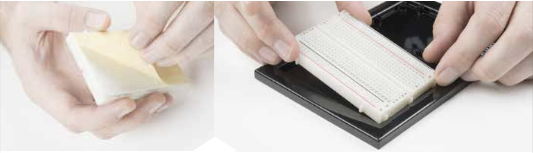
PEEL the adhesive backing off the breadboard.
CAREFULLY ALIGN the breadboard over its spot on the baseplate. The text on the breadboard should face the same direction as the text on the baseplate. Firmly press the breadboard to the baseplate to adhere it.
Install the RedBoard
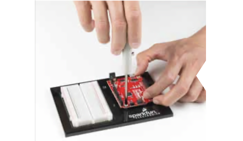
ALIGN THE REDBOARD with its spot on the baseplate. The text on it should face the same direction as the text on the breadboard and the baseplate. Using one of the two included screws, affix the RedBoard to one of the four stand-off holes found on the baseplate. The plastic holes are not threaded, so you will need to apply pressure as you twist the screwdriver.
Screw the second screw in the stand-off hole diagonally across from the first. With that, your baseplate is now assembled.
Anatomy of the SparkFun RedBoard
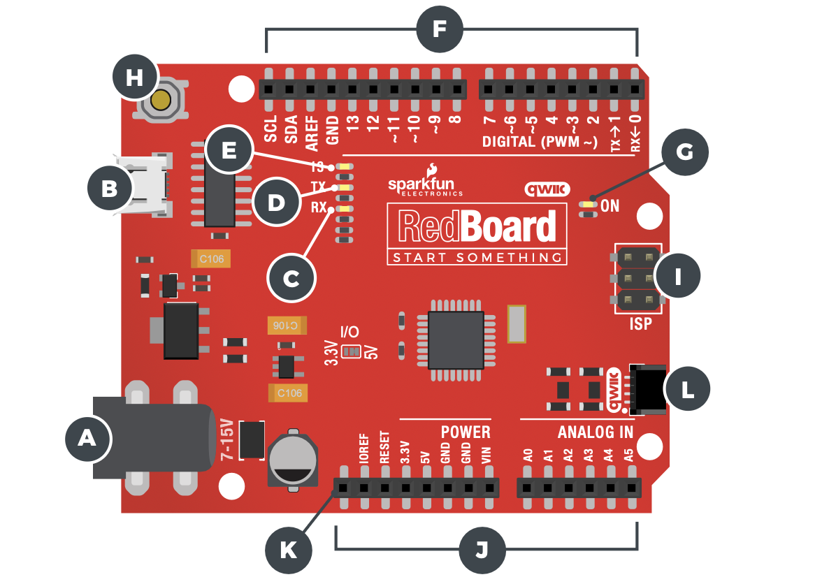
REDBOARD HARDWARE OVERVIEW
| A | POWER IN (BARREL JACK) | Can be used with either a 9V or 12V “wall-wart” or a battery pack. |
| B | POWER IN (USB-C PORT) | Provides power and communicates with your board when plugged into your computer via USB. |
| C | LED (RX: RECEIVING) |
Shows when the USB-to-serial chip is receiving data bits from the computer. |
| D | LED (TX: TRANSMITTING) |
Shows when the USB-to-serial chip is transmitting data bits to the computer. |
| E | ONBOARD LED PIN D13 |
This LED, connected to digital pin 13, can be controlled in your program and is great for troubleshooting. |
| F | PINS AREF,GROUND, DIGITAL,RX, TX, SDA, SCL | These pins can be used for inputs, outputs, power and ground. |
| G | POWER LED | Illuminated when the board is connected to a power source. |
| H | RESET BUTTON | A manual reset switch that will restart the RedBoard and your code. |
| I | ISP HEADER | This is the In-System Programming header. It is used to program the ATMega328 directly. It will not be used in this guide. |
| J | ANALOG IN, VOLTAGE IN, GROUND, 3.3 AND 5V OUT, RESET | The power bus has pins to power your circuits with various voltages. The analog inputs allow you to read analog signals. |
| K | RFU | This stands for Reserved for Future Use. |
| L | QWIIC CONNECTOR | SparkFun Qwiic® Cable Connector for I2C Devices. |
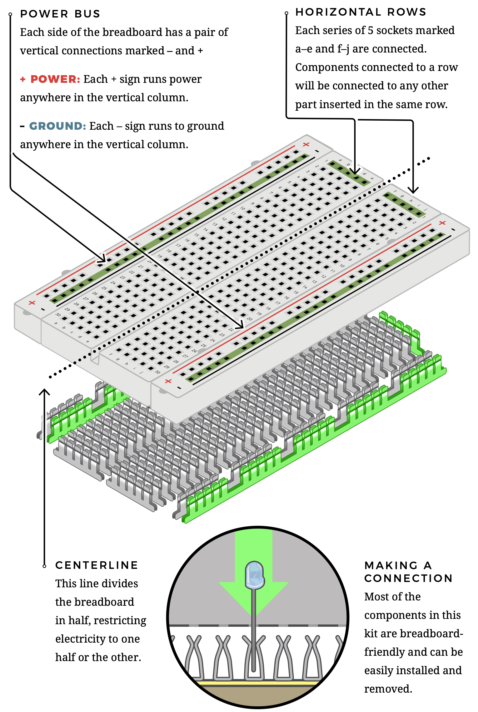
Anatomy of the Breadboard
A breadboard is a circuit-building platform that allows you to connect multiple components without using a soldering iron.
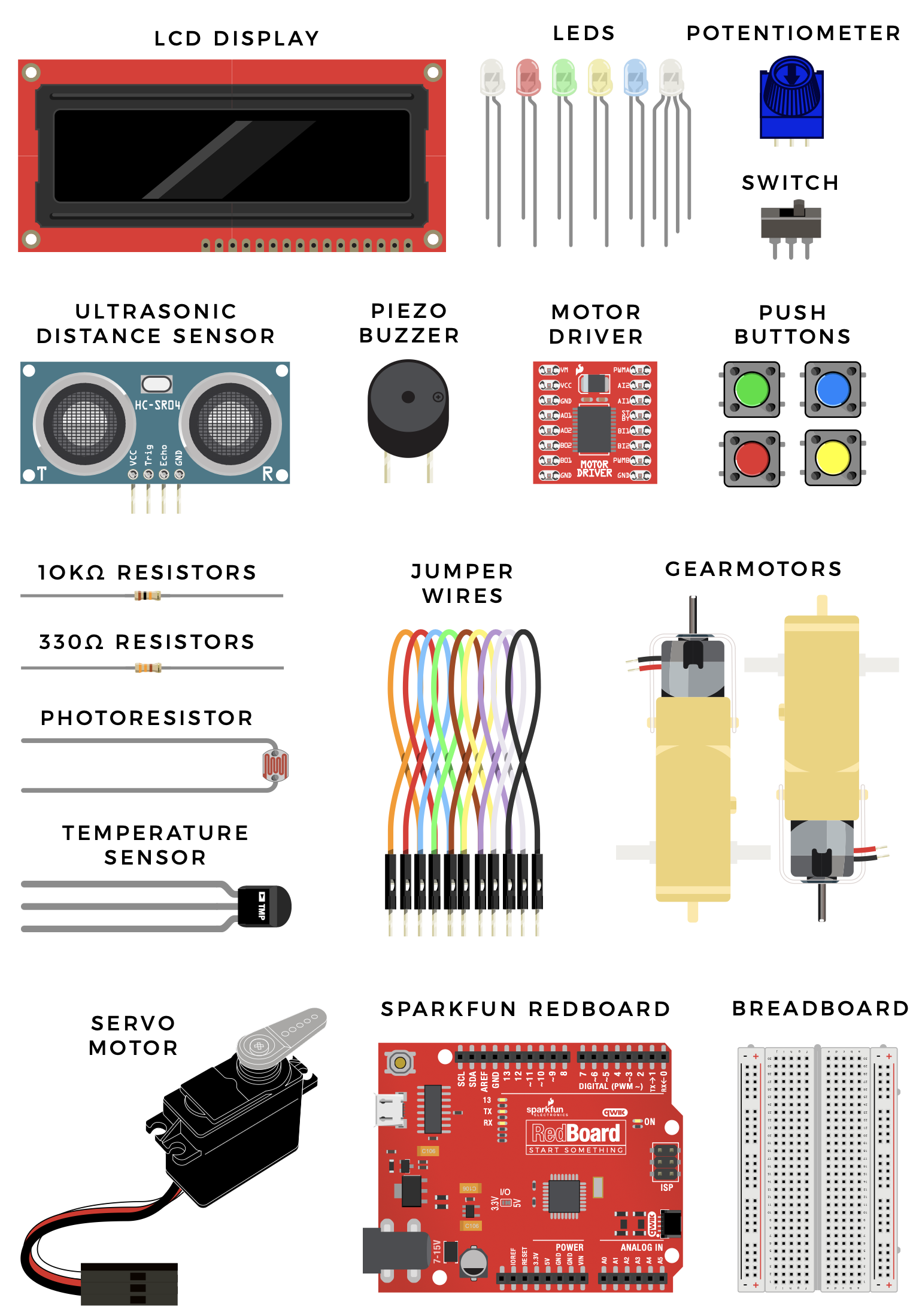
Inventory of Parts
The SparkFun Inventor’s Kit contains an extensive array of electronic components. As you work your way through each circuit, you will learn to use new and more complicated parts to accomplish increasingly complex tasks.