Project 1 - Circuit 1A: Blinking an LED
You can find LEDs in just about any source of light, from the bulbs lighting your home to the tiny status lights flashing on your home electronics. Blinking an LED is the classic starting point for learning how to program embedded electronics. It’s the “Hello, World!” of microcontrollers. In this circuit, you’ll write code that makes an LED blink on and off.

New Components
Light-Emitting Diodes (LEDs)
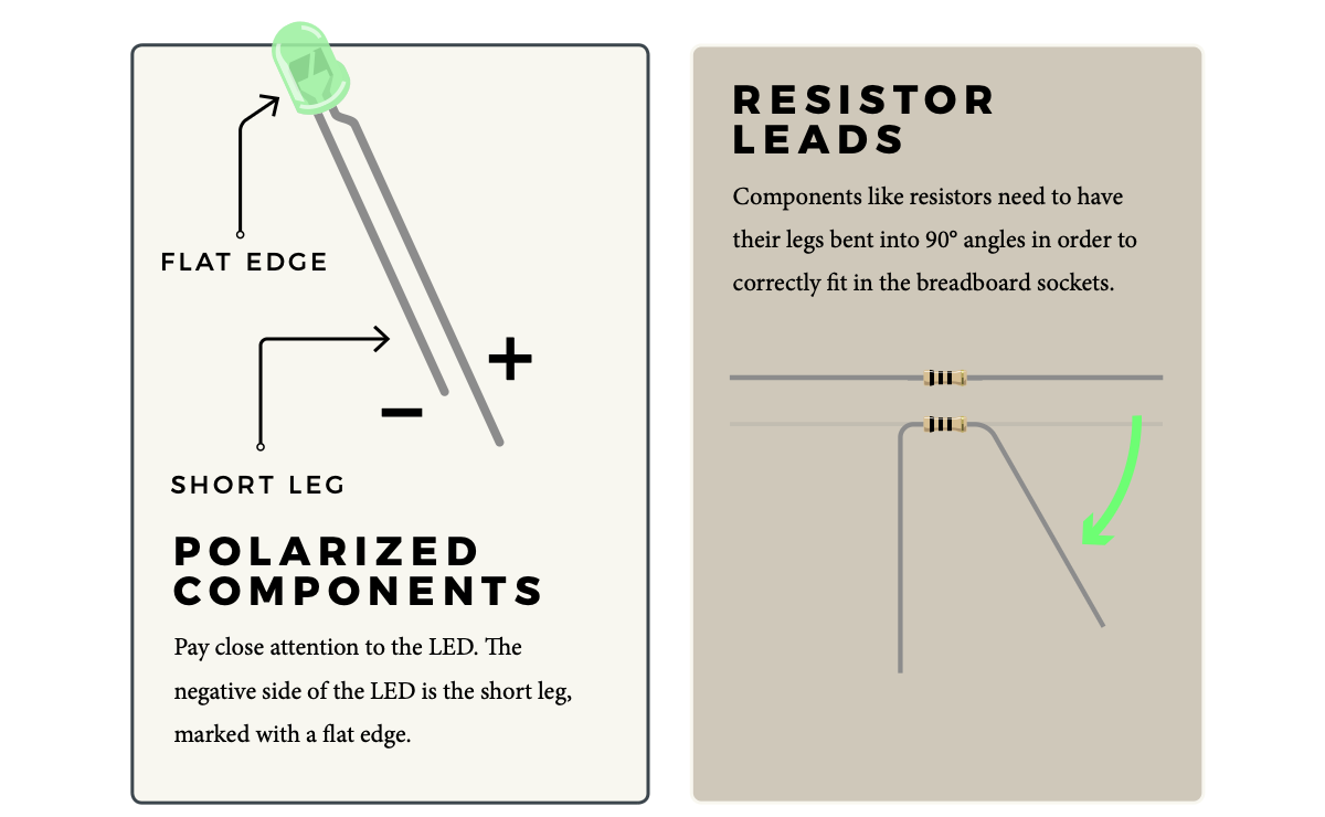
LEDs are small lights made from a silicon diode. They come in different colors, brightnesses and sizes. LEDs (pronounced el-ee-dees) have a positive (+) leg and a negative (-) leg, and they will only let electricity flow through them in one direction. LEDs can also burn out if too much electricity flows through them, so you should always use a resistor to limit the current when you wire an LED into a circuit.

Resistors
Resistors resist the flow of electricity. You can use them to protect sensitive components like LEDs. The strength of a resistor (measured in ohms) is marked on the body of the resistor using small colored bands. Each color stands for a number, which you can look up using a resistor chart. One can be found at the back of this book
New Concepts
Polarity
Many electronics components have polarity, meaning electricity can (and should) flow through them in only one direction. Polarized components, like an LED, have a positive and a negative leg and only work when electricity flows through them in one direction. Some components, like resistors, do not have polarity; electricity can flow through them in either direction.

OHM’s Law
OHM’S LAW describes the relationship between the three fundamental elements of electricity: voltage, resistance and current. This relationship can be represented by this equation:
V = I • R
V = Voltage in volts
I = Current in amps
R = Resistance in ohms (Ω)
This equation is used to calculate what resistor values are suitable to sufficiently limit the current flowing to the LED so that it does not get too hot and burn out.
Digital Output
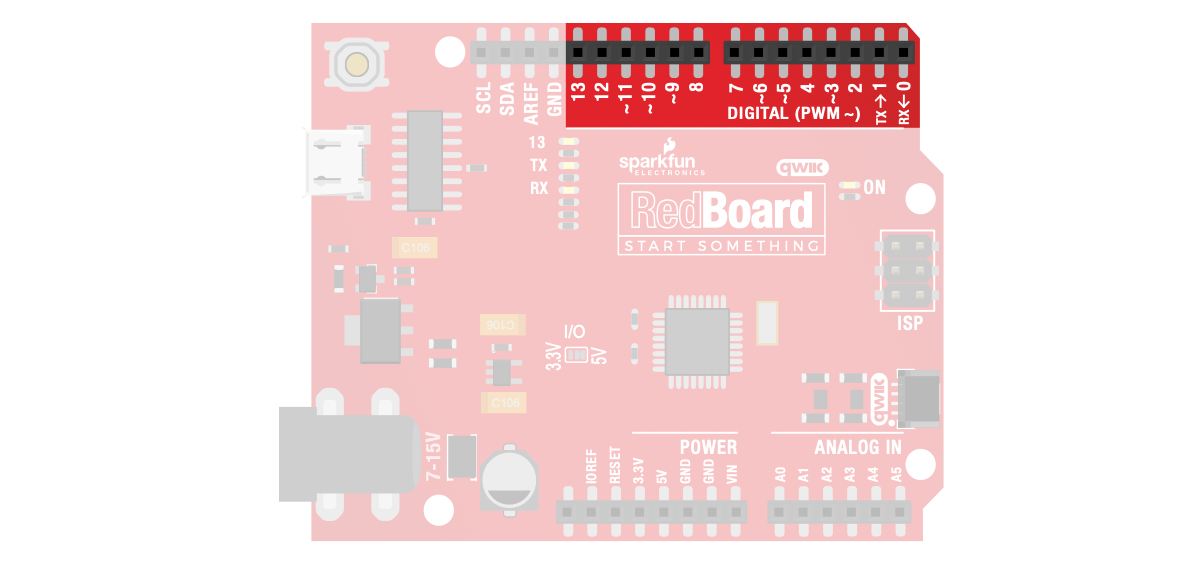
When working with microcontrollers such as the RedBoard, there are a variety of pins to which you can connect electronic components. Knowing which pins perform which functions is important when building your circuit. In this circuit, we will be using what is known as a digital output. There are 14 of these pins found on the RedBoard. A digital output only has two states: ON or OFF. These two states can also be thought of as HIGH or LOW, TRUE or FALSE. When an LED is connected to one of these pins, the pin can only perform two jobs: turning on the LED and turning off the LED. We’ll explore the other pins and their functions in later circuits.
New Ideas
ELECTRICAL SAFETY: Never work on your circuits while the board is connected to
a power source. The SparkFun RedBoard operates at 5 volts, which, while not enough to
injure you, is enough to damage the components in your circuit.
COMPONENT ORIENTATION & POLARITY: Instructions on how to orient each of
the new components will be given before each circuit diagram. Many components have
polarity and have only one correct orientation, while others are nonpolarized.
Hookup Guide
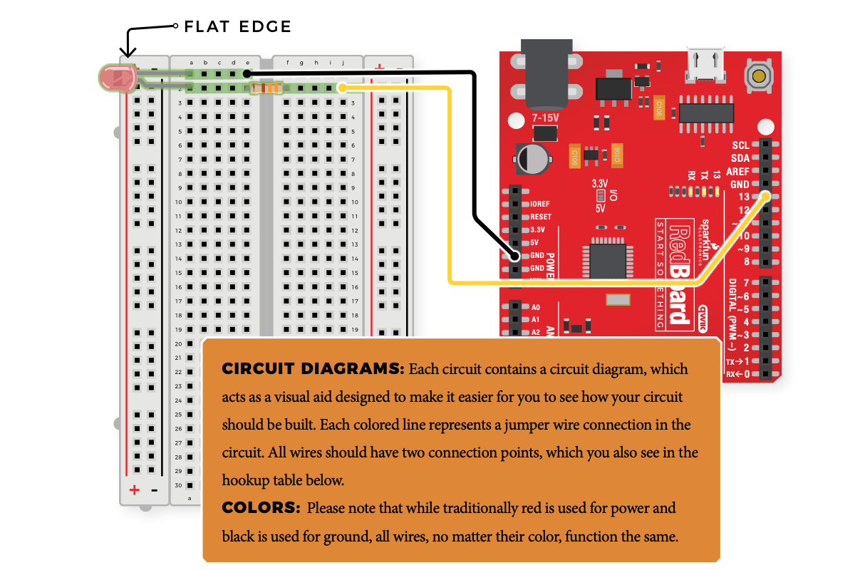
READY TO START HOOKING EVERYTHING UP? Check out the circuit diagram and hookup table below to see how everything is connected.
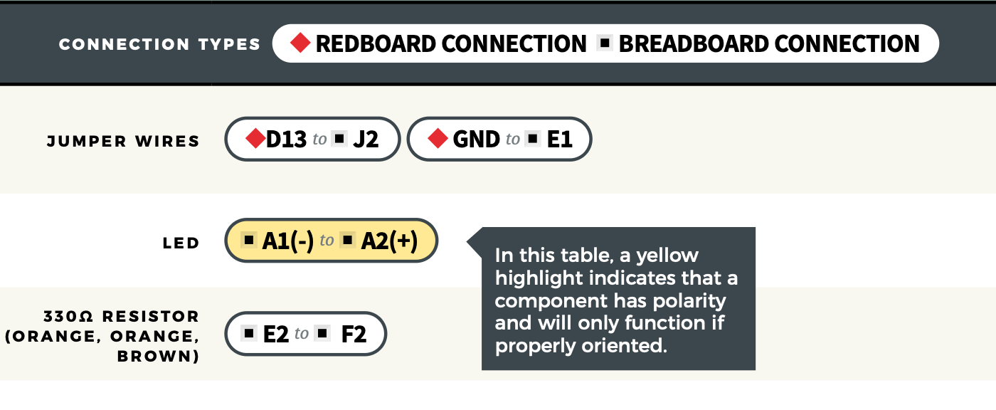
Hookup Tables
Many electronics beginners find it helpful to have a coordinate system when building their circuits. For each circuit, you’ll find a hookup table that lists the coordinates of each component or wire and where it connects to the RedBoard, the breadboard, or both. The breadboard has a letter/number coordinate system, just like the game Battleship.

…means one end of a component connects to digital pin 13 on your RedBoard and the other connects to J2 on the breadboard
Programming the RedBoard
The SparkFun RedBoard IoT is programmed using MicroPython and this project uses MicroPython commands to blink the LED just created circuit. Before this is possible, a MicroPython tool is needed to communcate with the ReadBoard.
Selecting a MicroPython Tool
The first step to enter commands on the RedBoard is to select a tool that allows direct interaction with MicroPython.
While a variety of methods exist to communicate with the RedBoard, the following tools are the most popular: Thonny, PyCharm and the command mpremote.
Once you select and install a tool, make sure your RedBoard is connected to your computer, and the micropython tool is connected to the RedBoard. Once connected, you should have access to the MicroPython REPL command line.
Entering MicroPython Commands
Step 1 - Setup
To blink the LED, we need to enable the board pin 34 (the pin that the LED is connected to in the circuit).
To do this we load the Pin definition for the board
from machine import Pin
Now create a Pin variable for the LED pin, number 13. Also define it as an output pin, so we can turn it on and off
led_pin = Pin(34, Pin.OUT)
We turn the LED on by setting the pin value to high or on
led_pin.high()
And to turn the LED off, we set the pin to low
led_pin.low()
To blink the LED, we can turn it on, wait a period of time and then turn it off. This is done by sleeping between the on and off commands.
To do this in MicroPython, we need a sleep function. Let’s load the sleep function, which will sleep for a number of seconds..
from time import sleep
Now lets blink the LED - sleeping for 1 second between turning the LED on and off
led_pin.high()
sleep(1)
led_pin.low()
sleep(1)
led_pin.high()
sleep(1)
led_pin.low()
Now we have blinked the LED!
Now we’ll present the idea of a for loop. A loop repeats a statement for a number of specified times.
To blink our LED 10 times, use the following command:
for i in range(10):
    led_pin.high()
    sleep(1)
    led_pin.low()
    sleep(1)
When this command runs, it blinks the LED 10 times by setting the LED high, then low and sleeping inbetween each step.
You’ve Completed Circuit 1A!
Continue to circuit 1B to learn about analog signals and potentiometers

There is another way – Jupyter Notebook version
Example of a Jupyter Notebook of this page, plus code is available here: